
Page 5 of 15
2013-2014 Research
Shielded Multi-Layer Caduceus Coil Sensor Tests
Tony Devencenzi 2013-11-28 and 2013-11-29
Sensors Tested – Shielded Multi-Layer 4 Cross Points (each Side), Caduceus Coil and Aether-Magnetic Sensor with standard 50VA transformer.
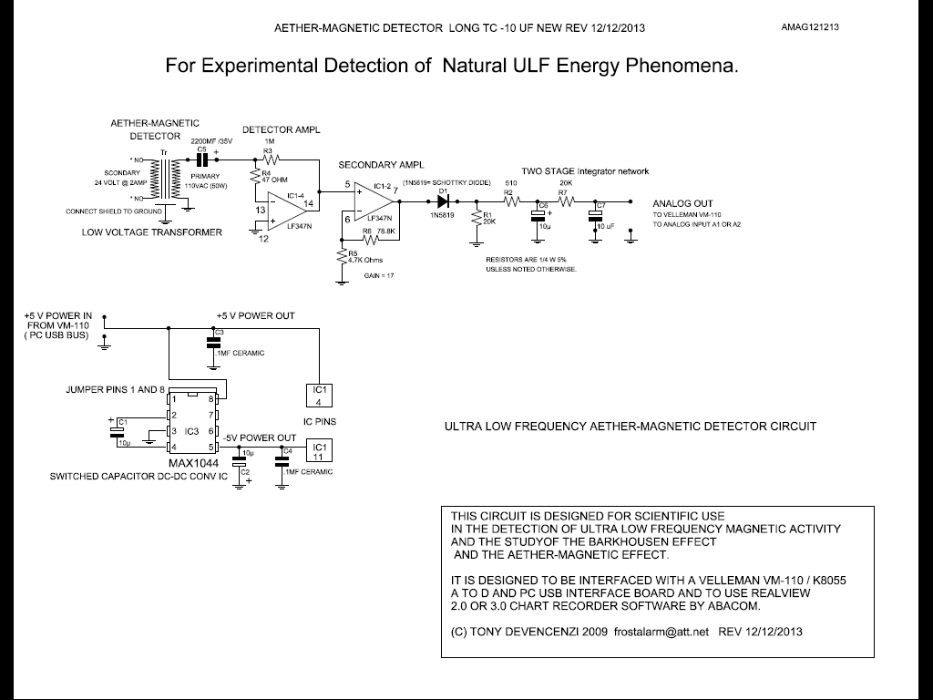
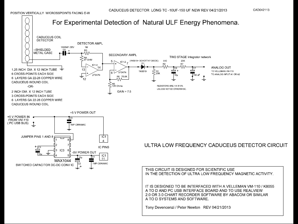
Circuit’s used – (Caduceus Coil Circuit with 1000 uF capacitor in series with the multi-layer caduceus coil. Long Time Constant output filter circuit, with 10 uF and 150 uF capacitors. / Aether-Magnetic circuit: 2200 uF sensor series capacitor and dual 10 uF Long Time Constant output circuit.)
Aether-Magnetic Circuit \Circuits\amag121213.pdf
Shielded Caduceus Coil Circuit \Circuits\cad042113.pdf
Duration of Test – Two days, Two tests, 24 hours each.
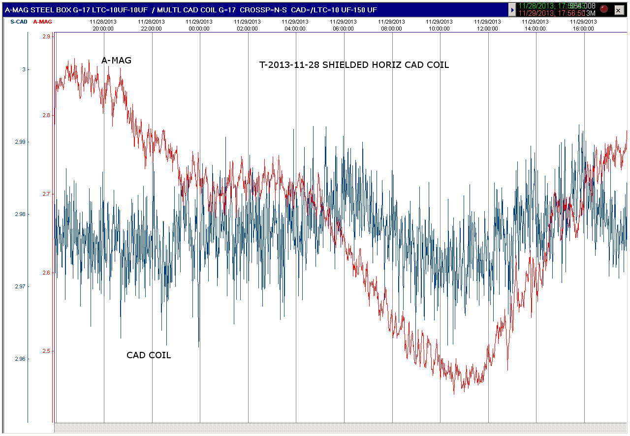
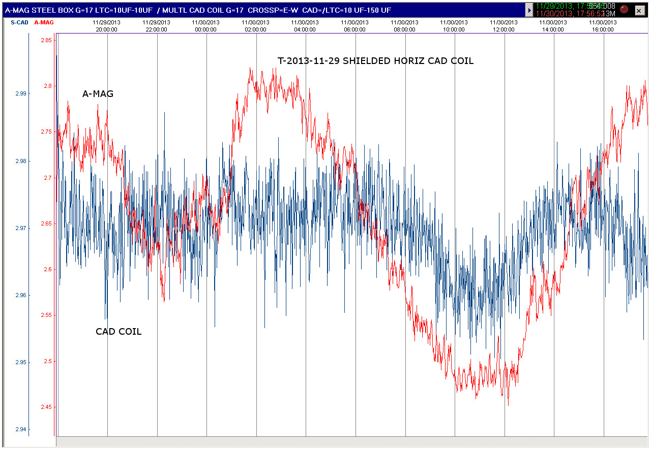
Purpose of Test – To compare Cross Points facing North-South on day one, with crosspoints facing East-West on Day two. ( Both days, coil was positioned horizontally). The Aether-Magnetic transformer was also positioned so that on day one its lamination flat sides were facing North-South and on day two facing East-West.
Findings – With the Caduceus Coil Cross Points facing East-West (and the aether-magnetic sensor's transformer lamination flat sides, facing East-west), each sensors had a higher and more defined. Output. In the second half of each recording, both sensor's traces followed each other obviously.
Result Images
Shielded Multi-Layer Caduceus Coil / Aether-Magnetic Sensor N-S

Shielded Multi-Layer Caduceus Coil / Aether-Magnetic Sensor E-W
_____________________________________________________________________________________
Unshielded Multi-Layer Caduceus Coil Sensor Tests Points=E-W
Tony Devencenzi 2013-12-06 and 2013-12-08
Sensors Tested – Unshielded Multi-Layer Caduceus Coil with 3 Cross Points (each Side) and 4 layers of windings. Also used was the Steel Shielded Aether-Magnetic Sensor with standard 50VA transformer.
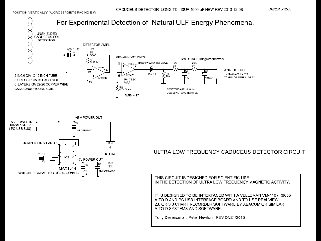
Circuit’s used – (Caduceus Coil Circuit with 1000 uF capacitor in series with the multi-layer caduceus coil. It had a Long Time Constant output filter circuit with dual10 uF capacitors for the First test and a Long Time Constant Circuit with 10 uF and 1000 uF capacitors for the Second test.
The Aether-Magnetic circuit: 2200 uF sensor series capacitor and dual 10 uF Long Time Constant output circuit.)
Aether-Magnetic Circuit \Circuits\amag121213.pdf
Unshielded Caduceus Coil Circuit First Test \Circuits\cad2013-12-06.pdf

Unshielded Caduceus Coil Circuit Second Test \Circuits\cad2013-12-08.pdf
Duration of Test – Two tests, 24 hours each.
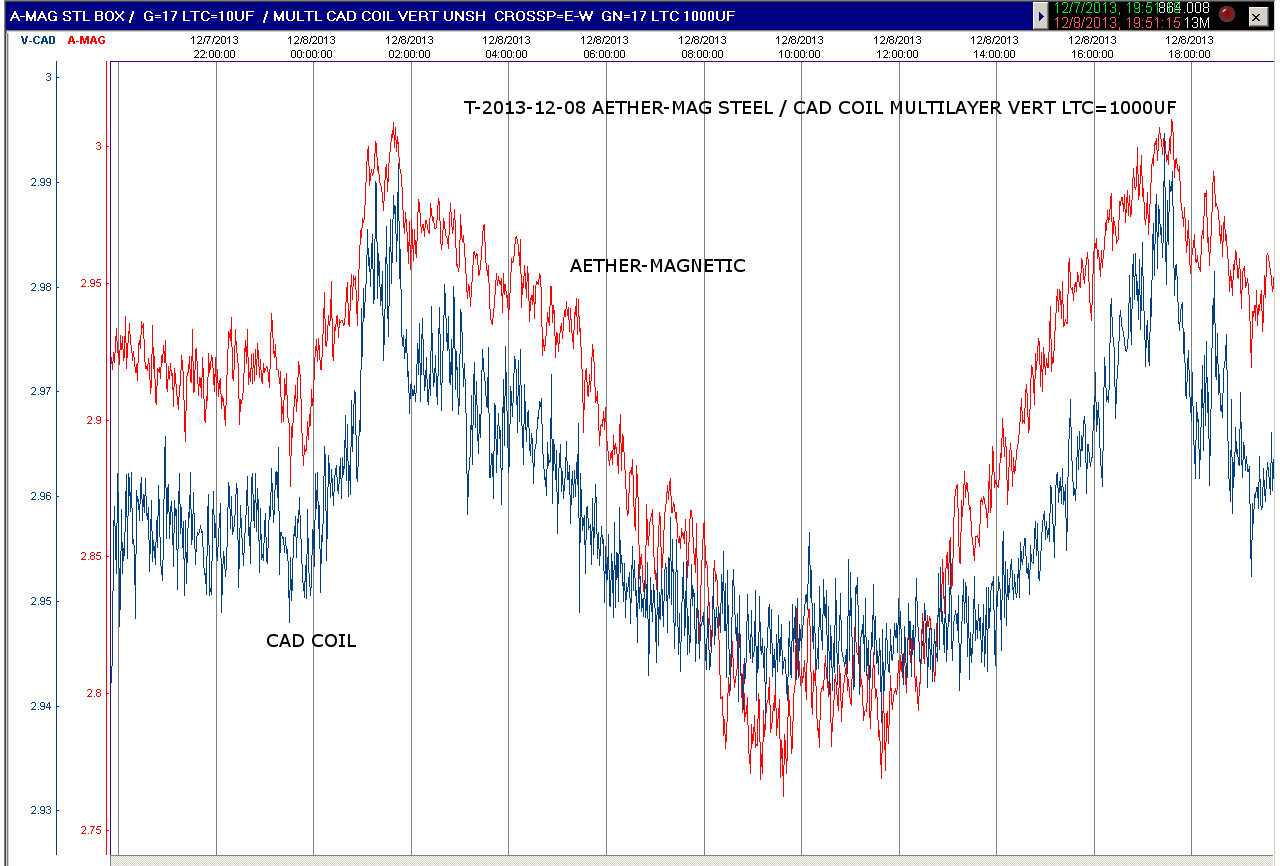
Purpose of Test – To test the output characteristics of an Unshielded Multi-Layer Vertical caduceus Coil in comparison to the Shielded Aether-Magnetic sensor. Also to compare a dual 10 uF output filter circuit with one that had 10 uF and 1000 uF capacitors.
Findings – The Unshielded caduceus Coil tracked the Aether-Magnetic Sensor wave in both lests. Both the dual 10 uF capacitor network in the first test and the 10 uF / 1000 uF capacitor network used in the second test, worked well, with a little loss of fine detail with the larger capacitor.
Result Images
Unshielded Multi-Layer Caduceus Coil / Aether-Magnetic Sensor E-W First Test
Unshielded Multi-Layer Caduceus Coil / Aether-Magnetic Sensor E-W Second Test
_____________________________________________________________________________________
Unshielded Vertical Phone Wire 7 Cross Point Caduceus Coil Sensor Tests
Tony Devencenzi 2013-12-08 to 2013-12-12
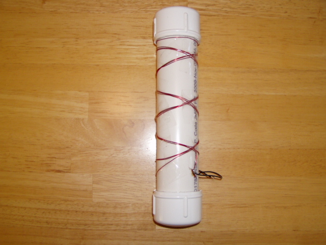
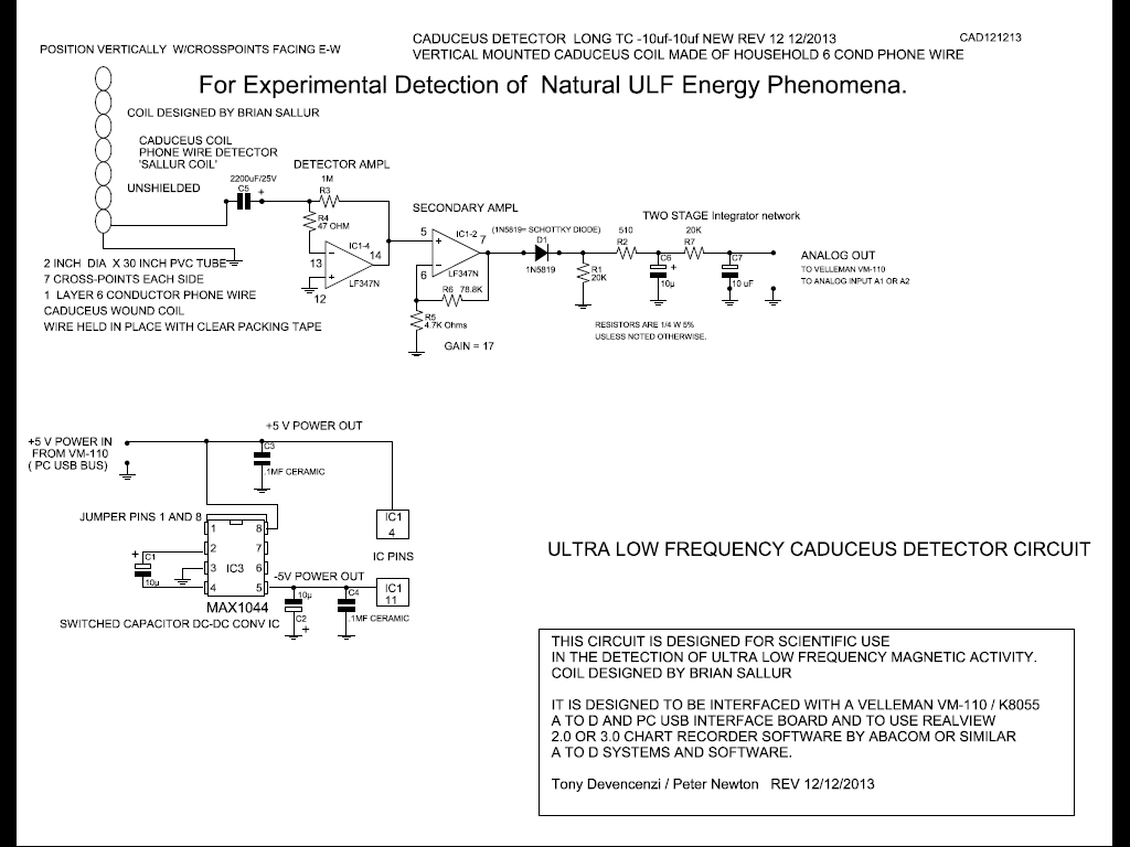
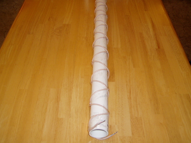
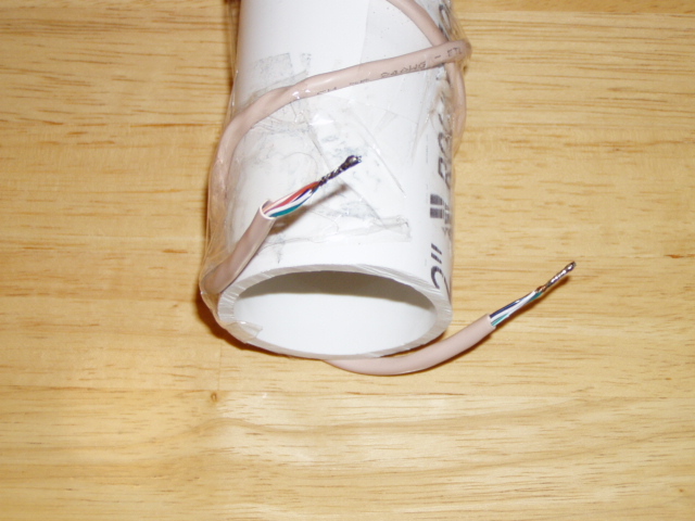
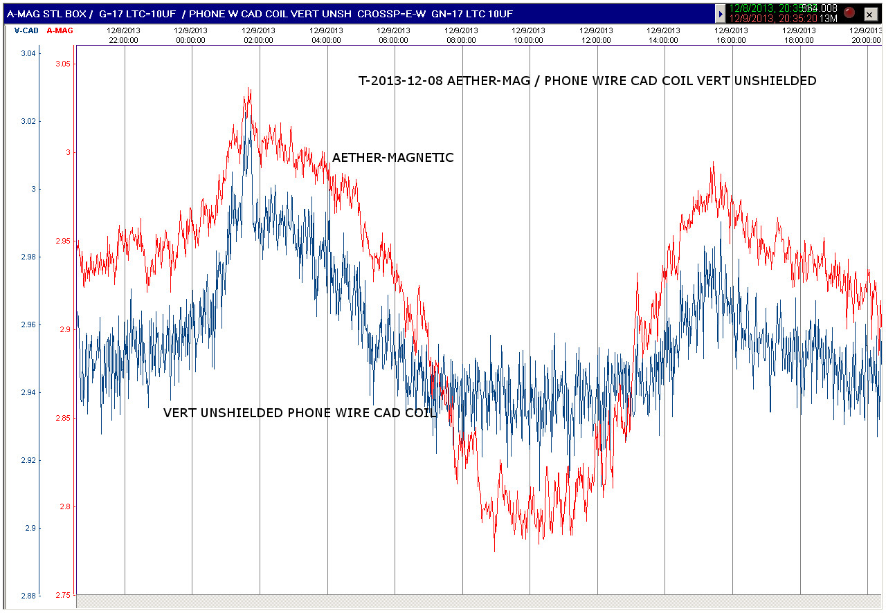
Sensors Tested – Vertical Mounted, Unshielded, Caduceus Coil (30 inch long, 7 crosspoints (each Side), Caduceus wound of 6 Conductor Phone Wire, One Layer each direction. 2 inches diameter. (This coil was Brian Sallur's last design). Note: All 6 ends of individual wires at each end of the cable, are connected together. / Aether-Magnetic Sensor with standard 50VA transformer. (Aether-Mag sensor is shielded).
Circuit’s used – (Caduceus Coil Circuit with 1000 uF capacitor in series with Cad Coil. Long Time Constant output filter circuit, with two 10 uF capacitors. / Aether-Magnetic circuit: 2200 uF sensor series capacitor and dual 10 uF Long Time Constant output circuit.)
Aether-Magnetic Circuit \Circuits\amag121213.pdf
Unshielded Vertical 30 Inch Long 7 Crosspoint Phone Wire Caduceus Coil and Circuit
Duration of Tests – Four 24 hour tests.
Purpose of Test – To compare Unshielded Unshielded Vertical Phone Wire Caduceus Coil to Shielded Aether-Magnetic Sensor. Also to compare Cad Coil crosspoint and ether-Magnetic lamination flat side, positions East-West to North-South.
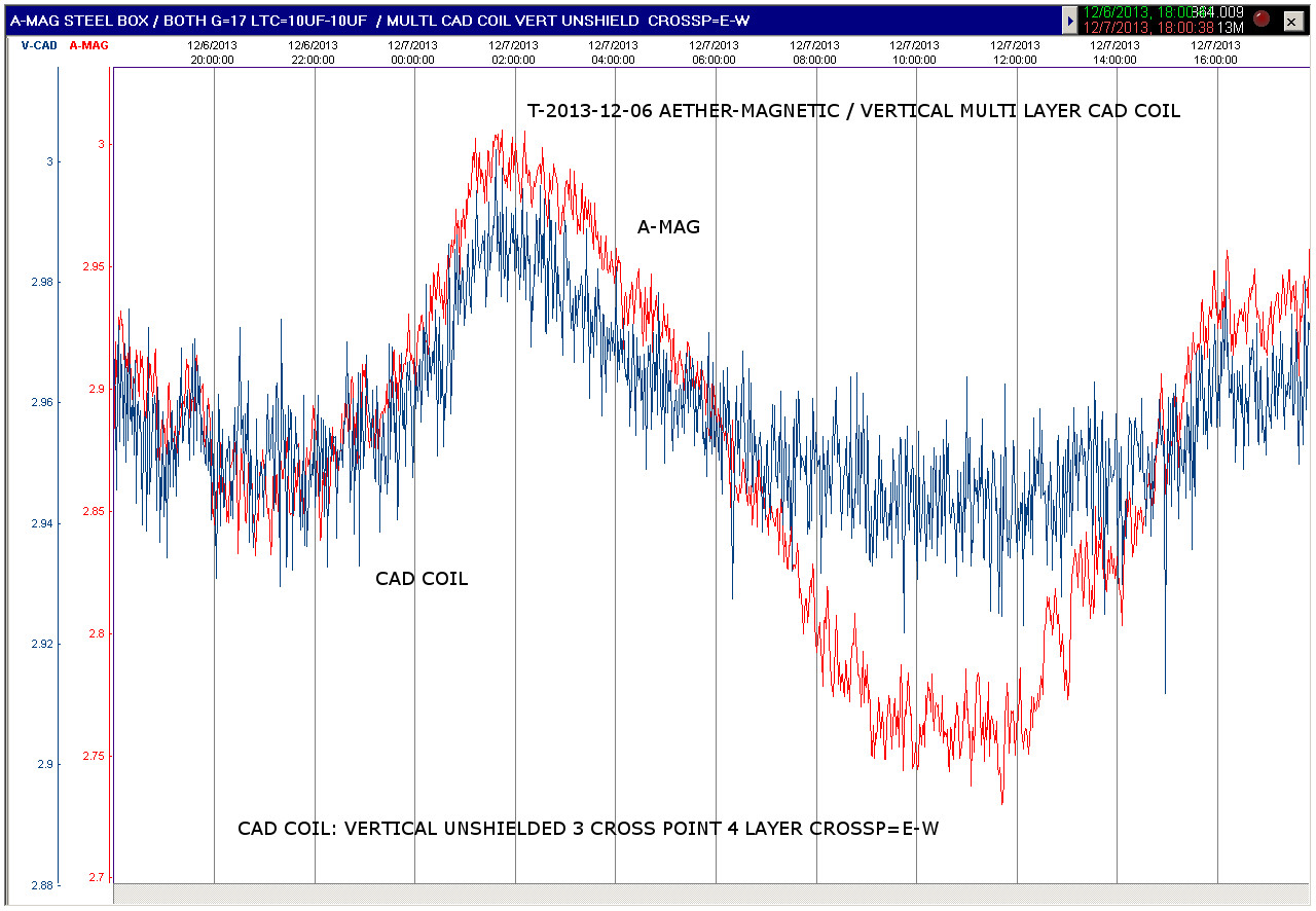
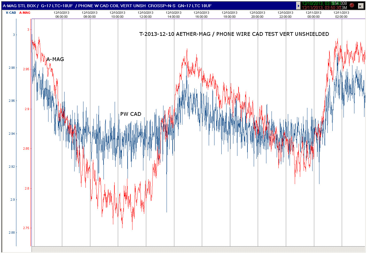
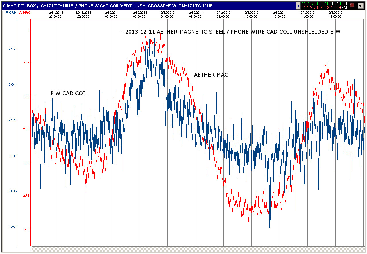
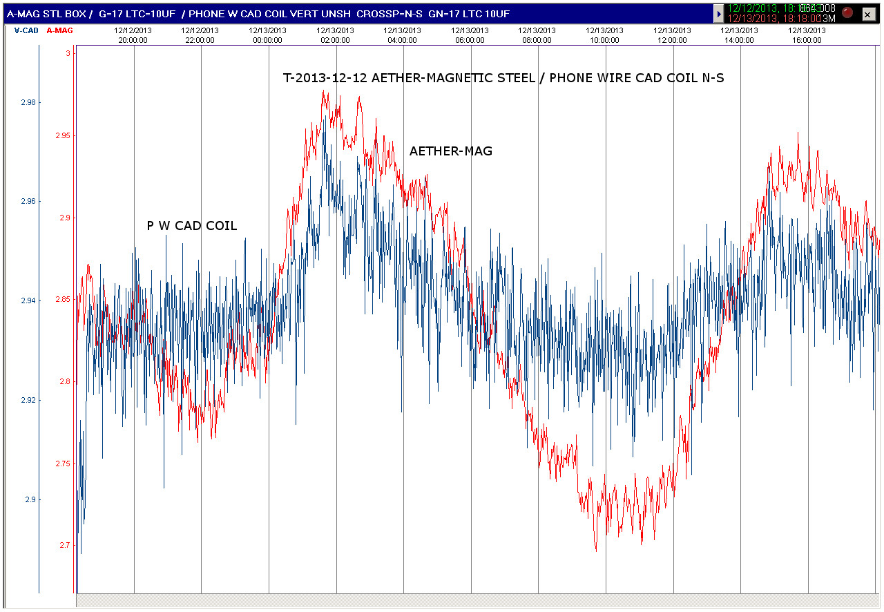
Findings – As Brian Sallur had discovered, the summing of all the conductors of the 6 wire cable, creates more virtual Cross Points and increases sensitivity. This Phone wire Cad Coil, is less direction sensitive than the other designs. The wave this Caduceus Coil records, tracks the Aether-Magnetic detector very well.
Result Images
Aether-Magnetic Sensor / Unshield Vert. 6 Cond. Phone Wire Caduceus Coil 7 Crosspoints=E-W

Aether-Magnetic Sensor / Unshield Vert. 6 Cond. Phone Wire Caduceus Coil 7 Crosspoints=N-S
Aether-Magnetic Sensor / Unshield Vert. 6 Cond. Phone Wire Caduceus Coil 7 Crosspoints=E-W
Aether-Magnetic Sensor / Unshield Vert. 6 Cond. Phone Wire Caduceus Coil 7 Crosspoints=N-S