Page 4 of 15
2013-2014 Research
Unshielded Horizontal 30 Inch Caduceus Coil Sensor Tests
Tony Devencenzi 2013-10-27 to 2013-11-04
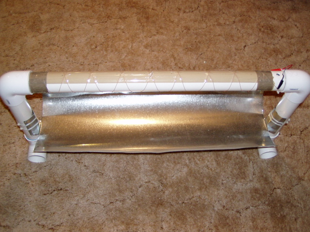
Sensors Tested – Horizontal Mounted, Unshielded, Caduceus Coil (30 inch long, 9 Cross Points (each Side), 20 GA. Magnet wire, One Layer each direction. 2 inches diameter. Galvanized Sheet Metal reflector Aprox. 10 inches below coil. This coil was Brian Sallur's very early design. / Aether-Magnetic Sensor with standard 50VA transformer. (Aether-Mag sensor is shielded in steel box).
Circuit’s used – (Caduceus Coil Circuit with 1000 uF capacitor in series with Cad Coil. Long Time Constant output filter circuit, with 10 uF and 150 uF capacitors. / Aether-Magnetic circuit: 2200 uF sensor series capacitor and dual 10 uF Long Time Constant output circuit.)
Aether-Magnetic Circuit \Circuits\amag121213.pdf

Unshielded 30 Inch Long Caduceus Coil and Circuit

Duration of Tests – One 24 hour test and one 72 hour test.
Purpose of Test – To compare Unshielded Horizontal Caduceus Coil to Shielded Aether-Magnetic Sensor. Also to compare Cad Coil crosspoint and ether-Magnetic lamination flat side, positions East-West to North-South.
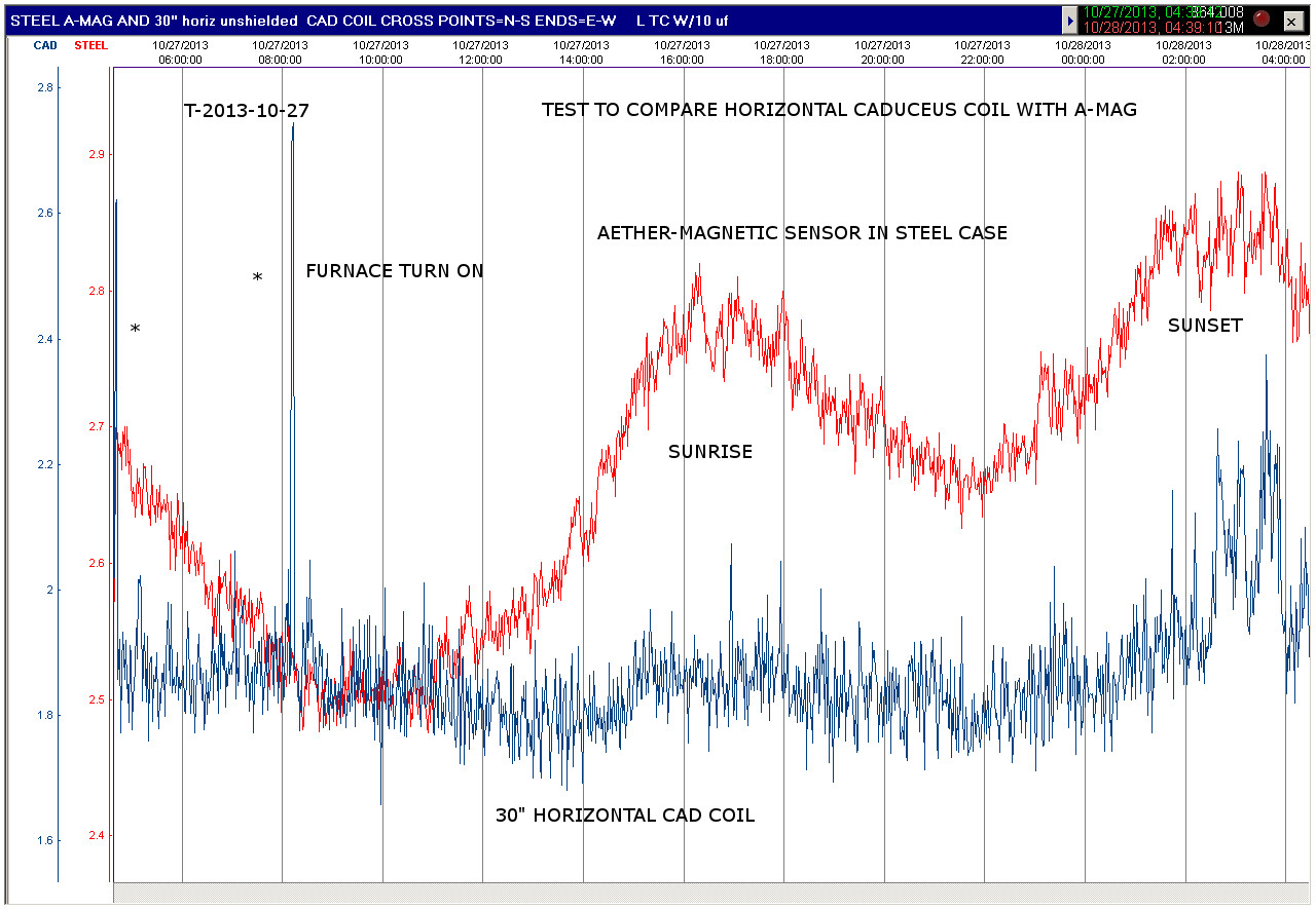
Findings – Test 1=24 hours, with the Caduceus Coil Cross Points facing North-South and tube ends facing East-West, the Caduceus Coil wave tracks the Aether-Magnetic sensor wave from about mid point of recording onward.
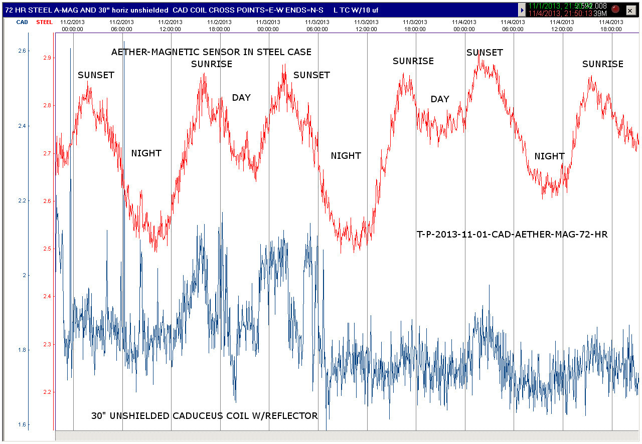
Test 2=72 hours, with Caduceus Coil Cross Points facing East-West and tube ends facing North-South, some Caduceus Coil wave tracking with the Aether-Magnetic sensor wave, is evident throughout the 3 day test.
Result Images
Unshielded, Single Layer, Horizontal Caduceus Coil / Aether-Magnetic Sensor Test one
Unshielded, Single Layer, Horizontal Caduceus Coil / Aether-Magnetic Sensor Test two

30 Inch Unshielded Horizontal Caduceus Coil Photo 1

30 Inch Unshielded Horizontal Caduceus Coil Photo 2
_____________________________________________________________________________________
Multi-Layer Caduceus Coil Tests
Peter Newton 2013-11-14 to 2013-11-17
Sensors Tested – Unshielded Multi-Layer Caduceus coil on one channel and an LM35 Solid State Temperature sensor on the other channel. In all tests, the Caduceus Coil Cross Points were positioned facing North-South.
Circuit’s used – Caduceus Coil circuit and LM35 Temperature Sensor. Note this test setup uses a Dataq DI-148 Analog to Digital Converter and USB interface device. The software, is Windaq Chart Recorder, which is included with the Dataq device.
Caduceus Coil Circuit (Unshielded, Mult-Layer, Vertical)

Duration of Test – Four Days, 24 hours each.
Purpose of Test – To record activity detected by the caduceus coil and compare with temperature fluxuations, within the same time span.
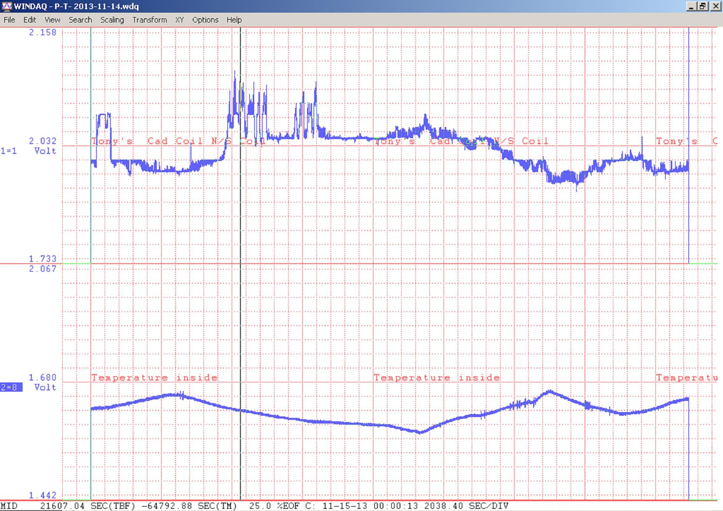
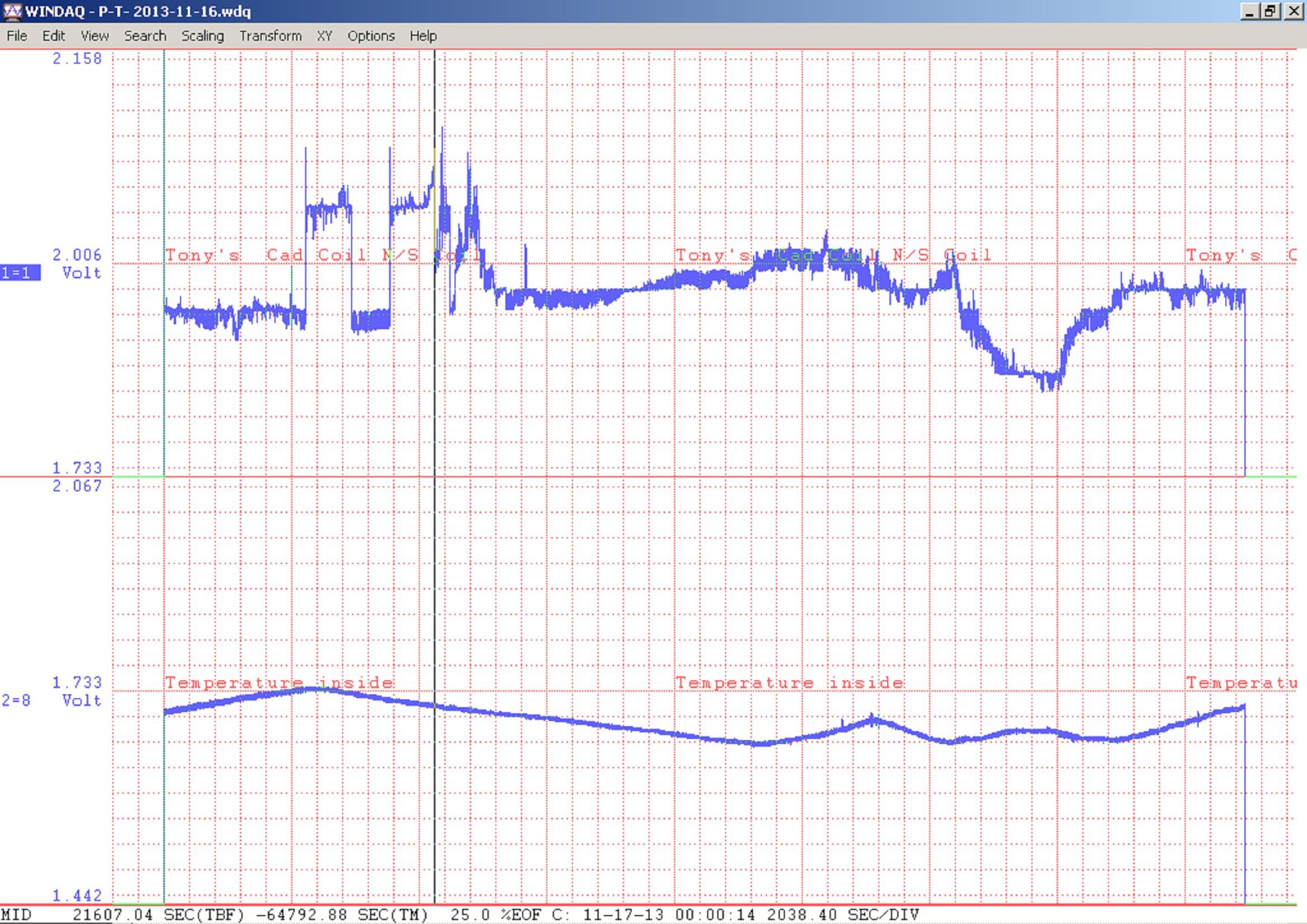
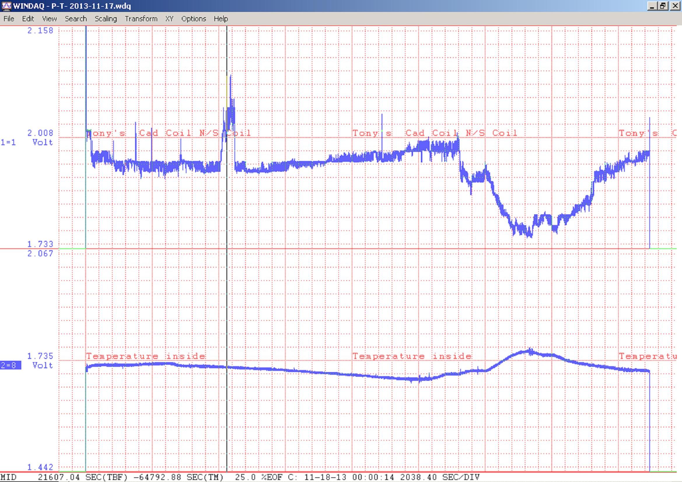
Findings – The Multi-Layer caduceus Coil records natural activity and what appears to be man made electrical activity as well. Some of the longer fluxuations, seem to reflect the changes in temperature recorded with the LM35 temperature sensor.
Result Images
Unshielded, Multi-Layer, Vertical Caduceus Coil Test 1

Unshielded, Multi-Layer, Vertical Caduceus Coil Test 2
Unshielded, Multi-Layer, Vertical Caduceus Coil Test 3
Unshielded, Multi-Layer, Vertical Caduceus Coil Test 4
_____________________________________________________________________________________
Multi-Layer Caduceus Coil Tests
Peter Newton 2013-11-22 to 2013-11-25
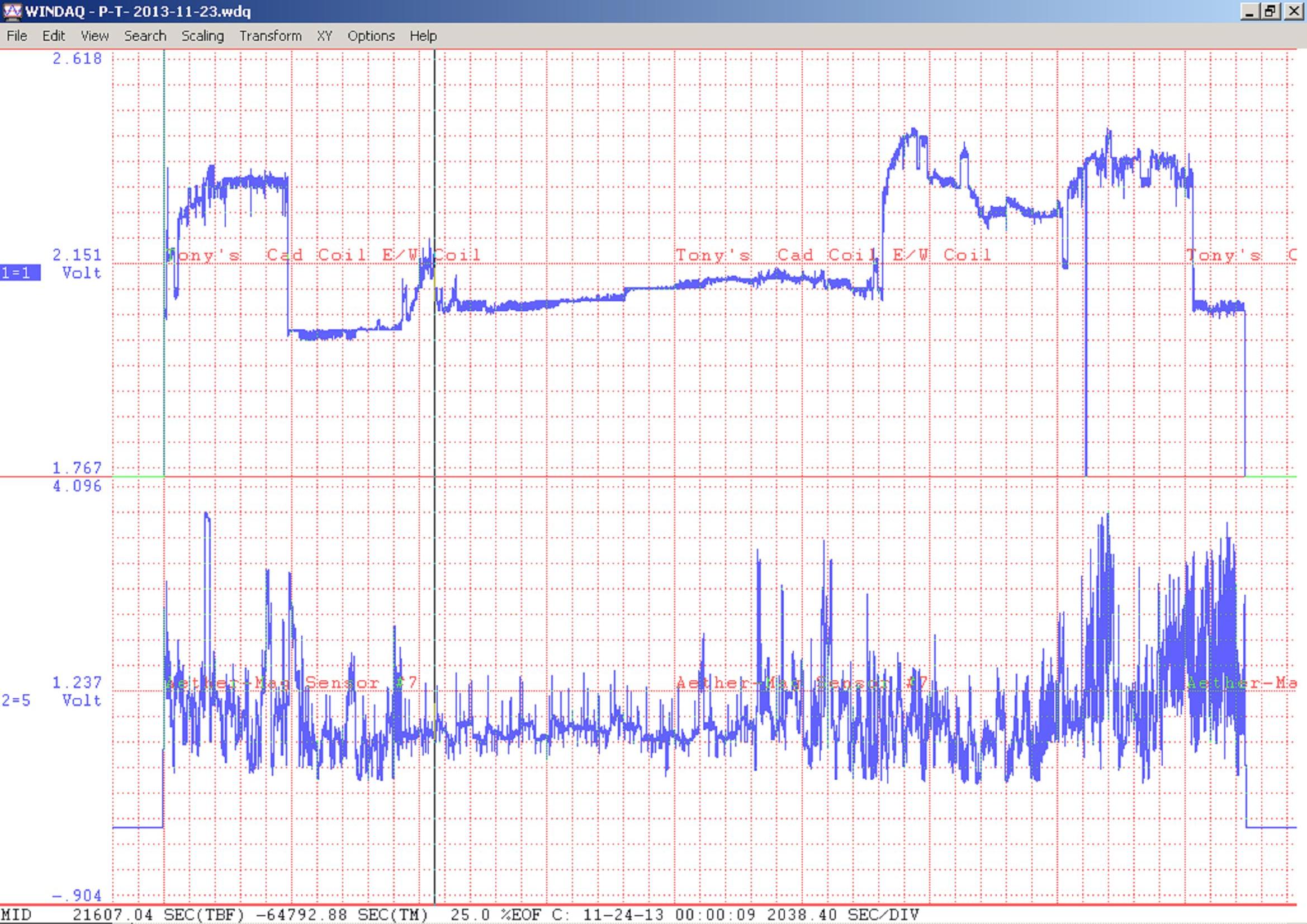
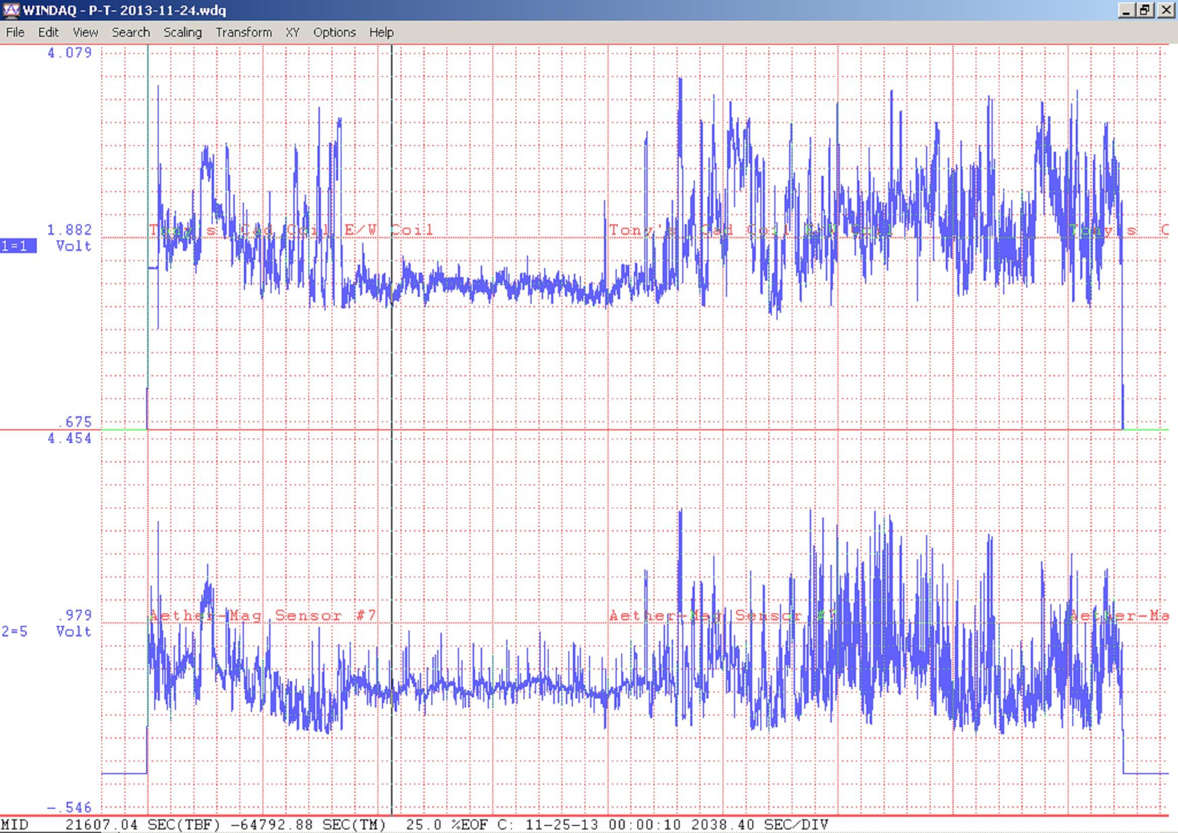
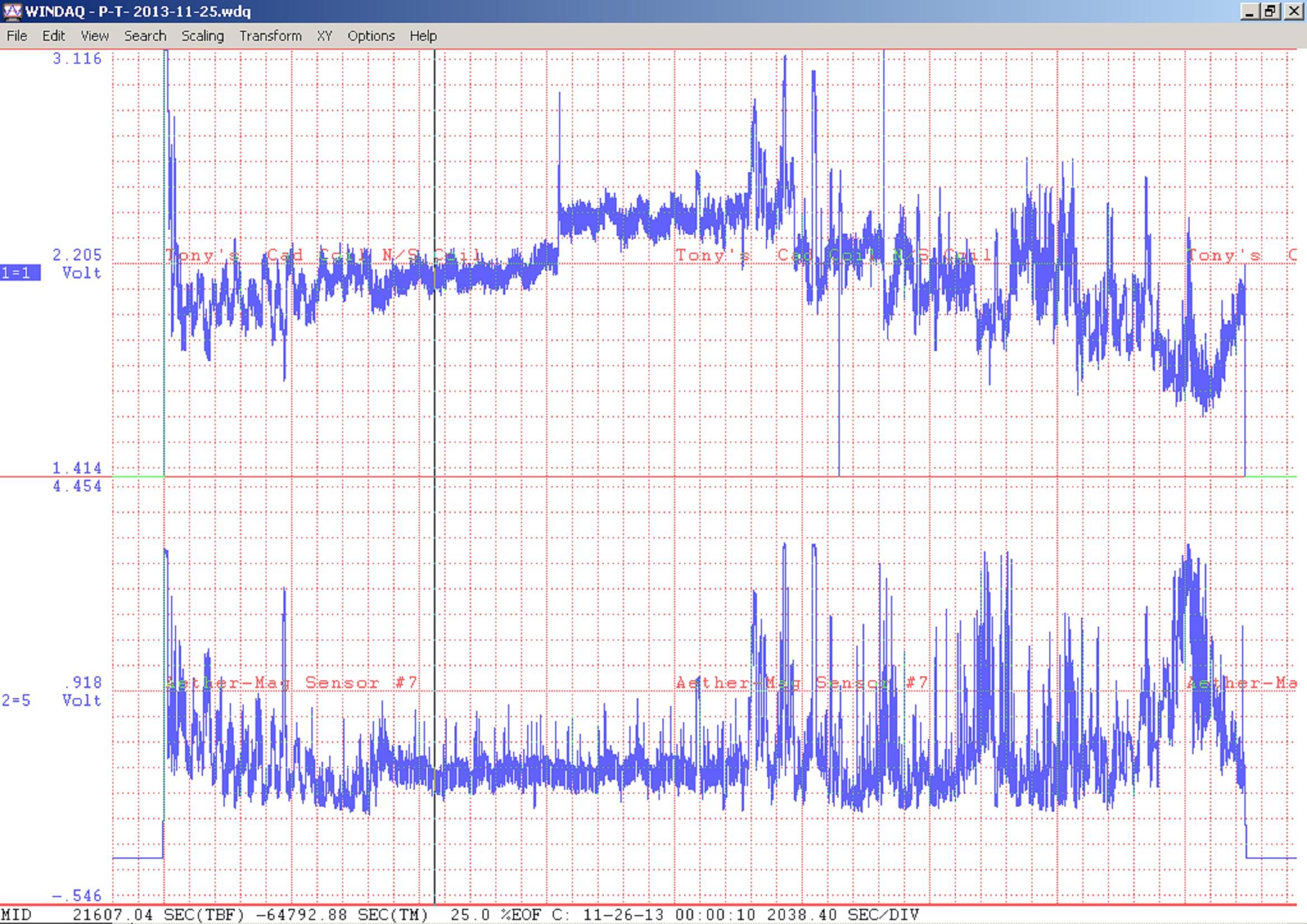
Sensors Tested – Unshielded Multi-Layer Caduceus coil on one channel and a Shielded Aether-Magnetic Sensor, on the other channel. In two tests, the Caduceus Coil Cross Points were facing East-West and in two tests, North-South.
Circuit’s used – Caduceus Coil circuit and an Aether-Magnetic Sensor circuit.. Note this test setup uses a Dataq DI-148 Analog to Digital Converter and USB interface device. The software, is Windaq Chart Recorder, which is included with the Dataq device.
Caduceus Coil Circuit (Unshielded, Mult-Layer, Vertical)
Aether-Magnetic Circuit \Circuits\amag121213.pdf
Duration of Test – Four Days, 24 hours each.
Purpose of Test – To record activity detected by the caduceus coil and the Aether-Magnetic Sensor and compare trends in common.
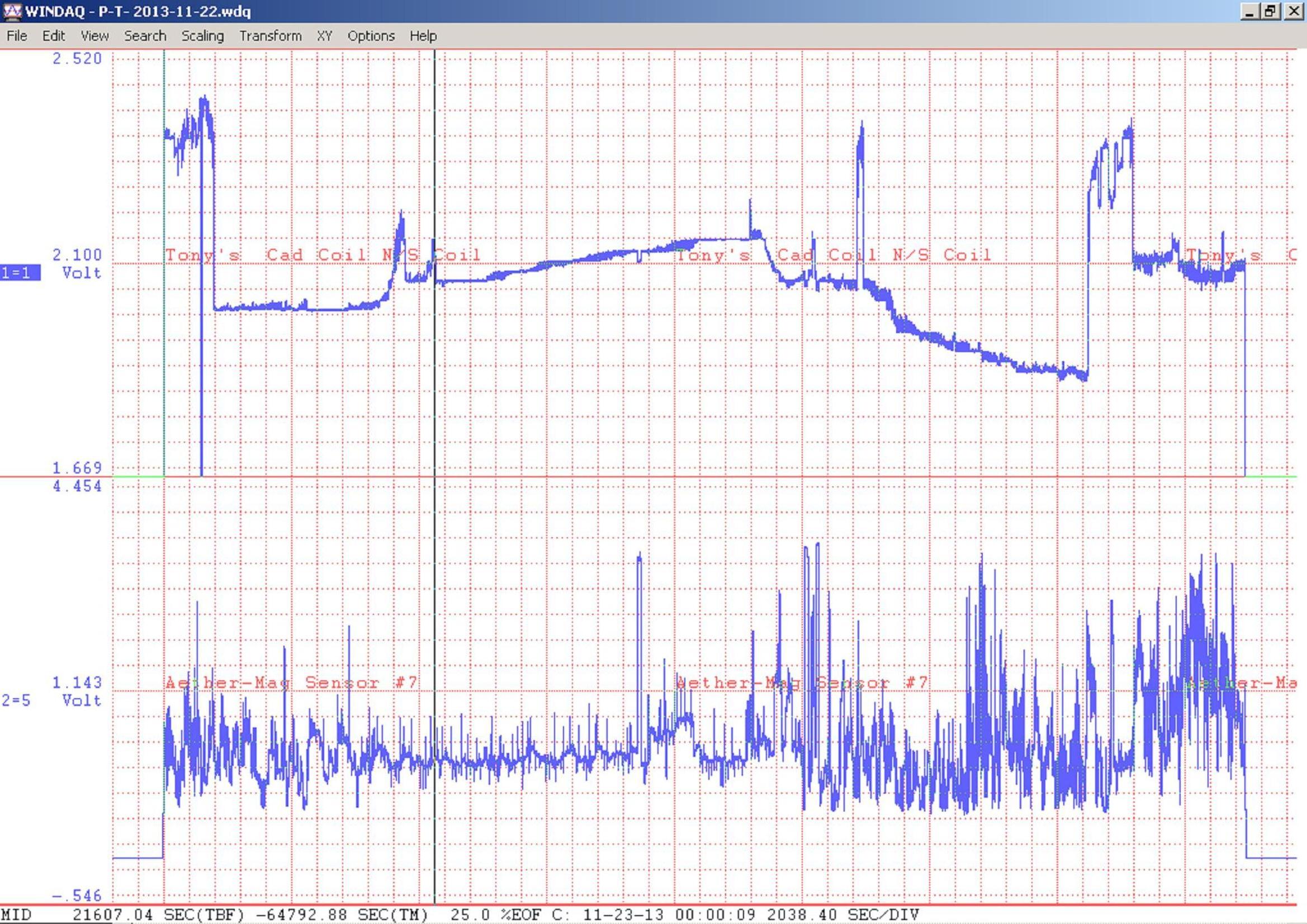
Findings – The First two days of recording, look quite different from the last two days, for some reason. The last two days, the Caduceus Coil seems to track the Aether-Magnetic Sensor better. Day three, is the closest matching day. Day four, has an interesting ripple wave on both sensors recordings.
Result Images
Unshielded, Multi-Layer, Vertical Caduceus Coil North-South Test 1

Unshielded, Multi-Layer, Vertical Caduceus Coil East-West Test 2
Unshielded, Multi-Layer, Vertical Caduceus Coil North-South Test 3
Unshielded, Multi-Layer, Vertical Caduceus Coil East-West Test 4