
Page 6 of 15
2013-2014 Research
E-Field Antenna Comparisons
Tony Devencenzi 2013-12-15 and 2013-12-16
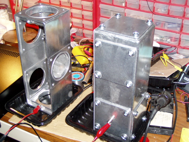
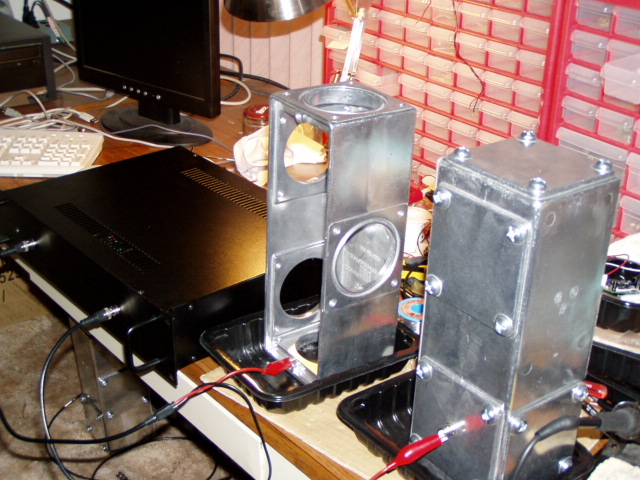
Sensors Tested – Dual E-Field Sensors. Tested with Telescoping Antenna, A 4 X 4 X 14 inch Junction Box “Frame” and also the complete Junction Box.
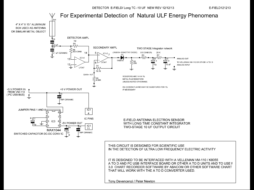
Circuit’s used – Standard E-Field circuit, with Long Time Constant output filter circuit and two 10 uF capacitors.
E-Field Circuit \Circuits\e-field121213.pdf
Duration of Test – Two tests, 24 hours each.
Purpose of Test – To test different antenna configurations, to see if sensitivity is proportional to surface area.
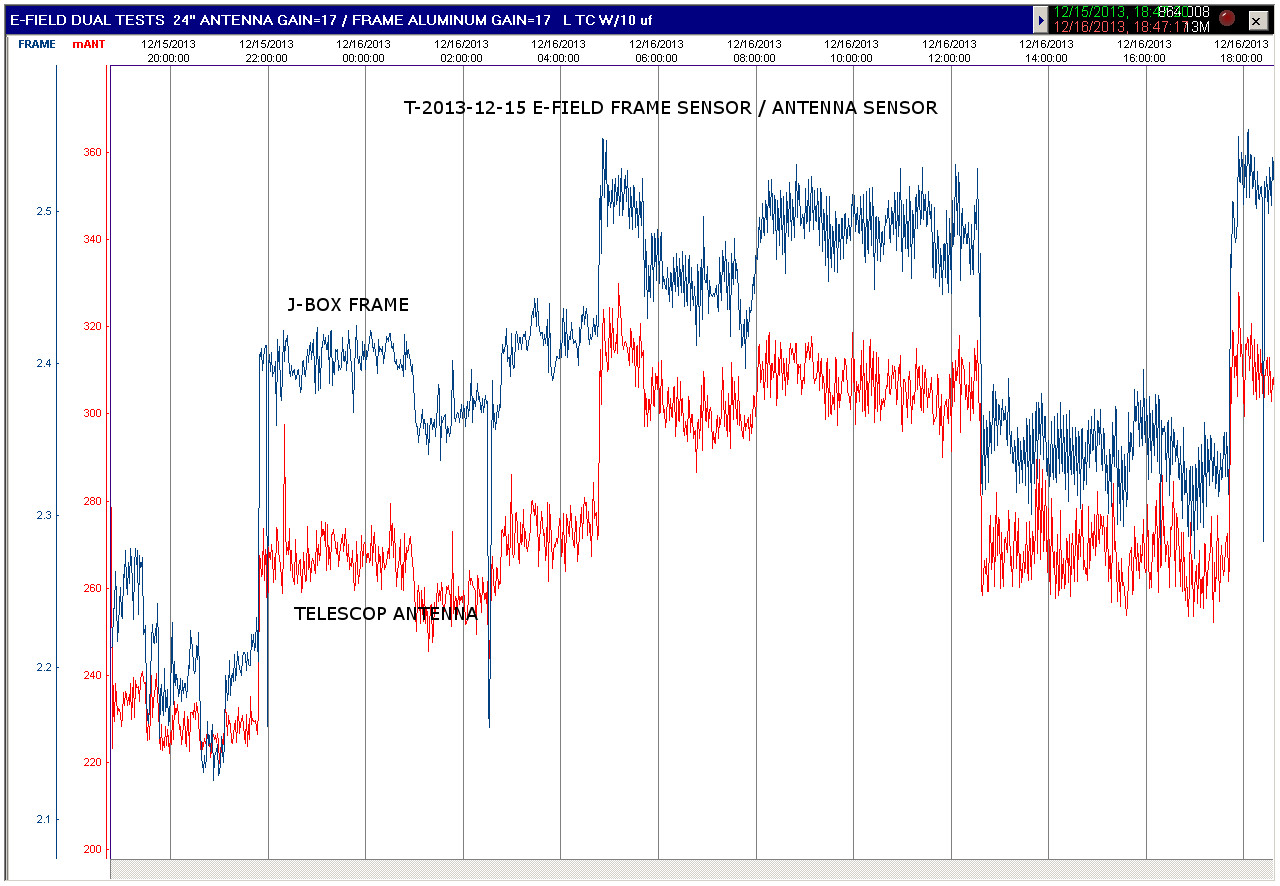
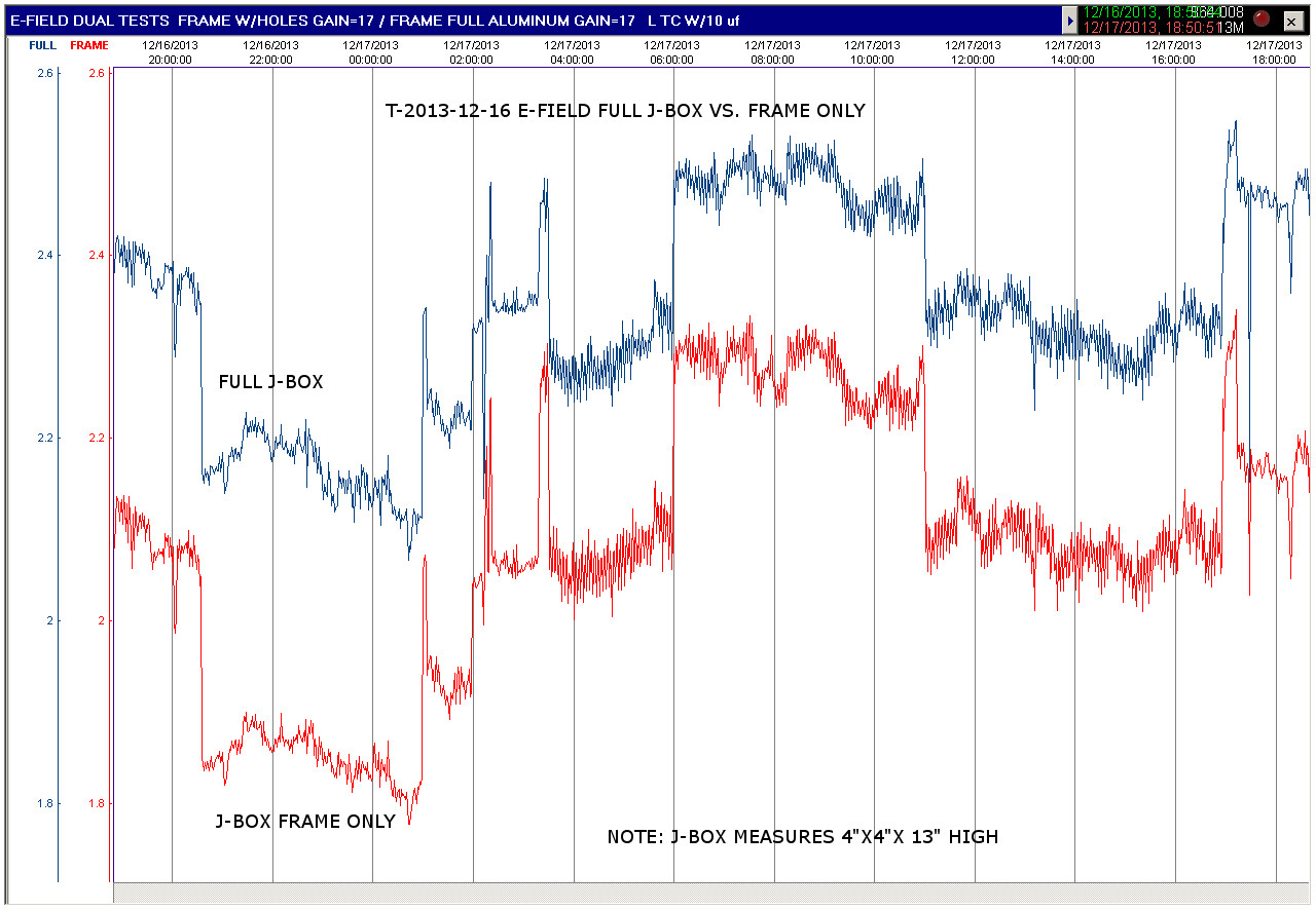
Findings – The 3E-Field circuit with the 6 inch telescoping antenna, had the lowest output. The same circuit, using a cast aluminum 4 X 4 X 14 inch junction box frame, had a higher output. The same circuit with the complete junction box, had the highest output. This show that the output is proportional to surface area of the antenna. Also it appears that the fine spike activity is slightly reduces as the surface area is increased. This is probably due to the fine spikes, being averaged out by the greater surface area.
Result Images
E-Field test Telescoping Antenna VS. Junction Box Frame
E-Field test Complete Junction Box Antenna VS. Junction Box Frame

E-Field test Junction Box Photo 1

E-Field test Junction Box Photo 2
_____________________________________________________________________________________
Vertical / Horizontal Phone Wire Caduceus Coil (Sallur Coil)
7 Cross Point Test
Peter Newton 2013-12-22
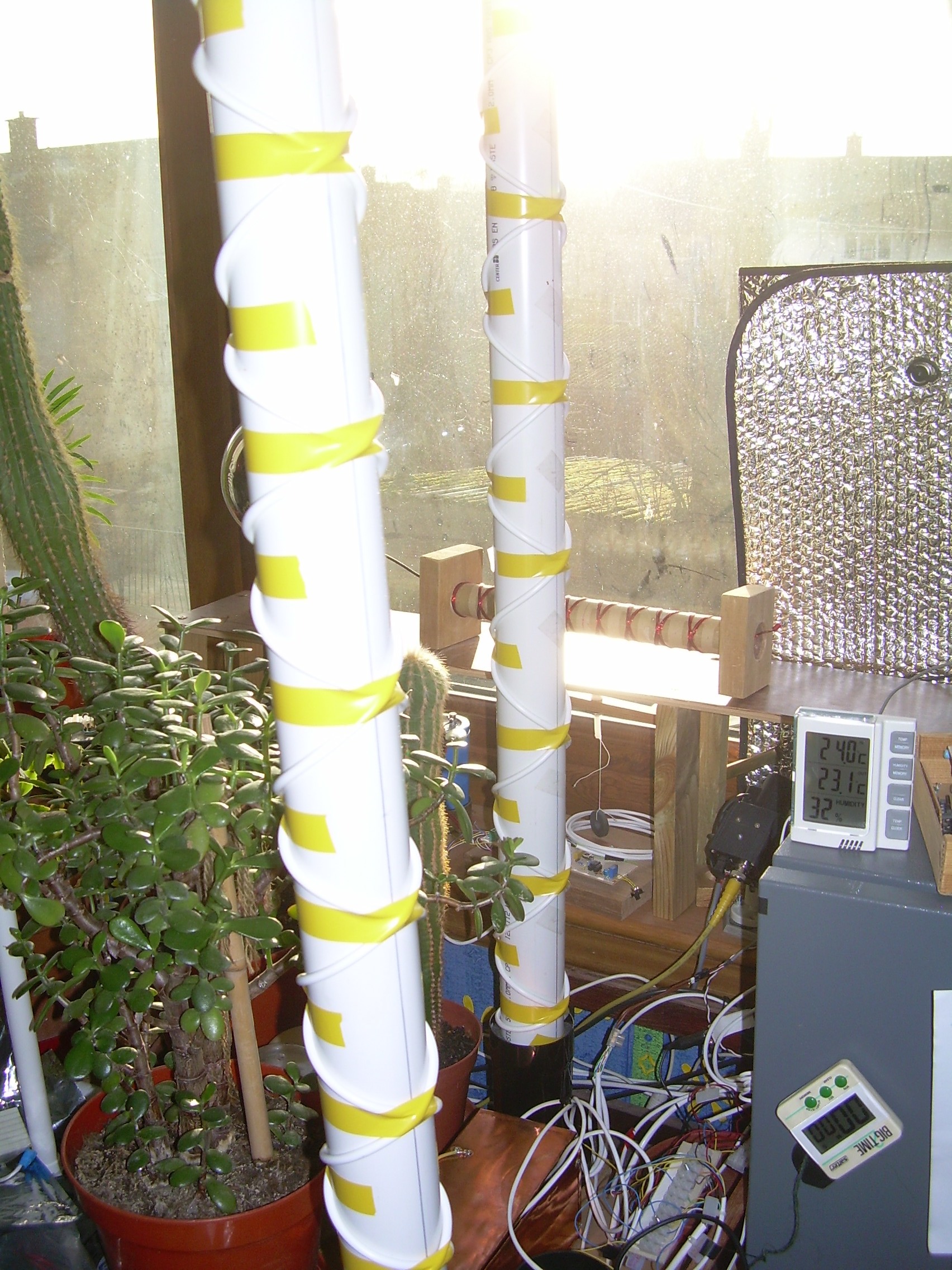
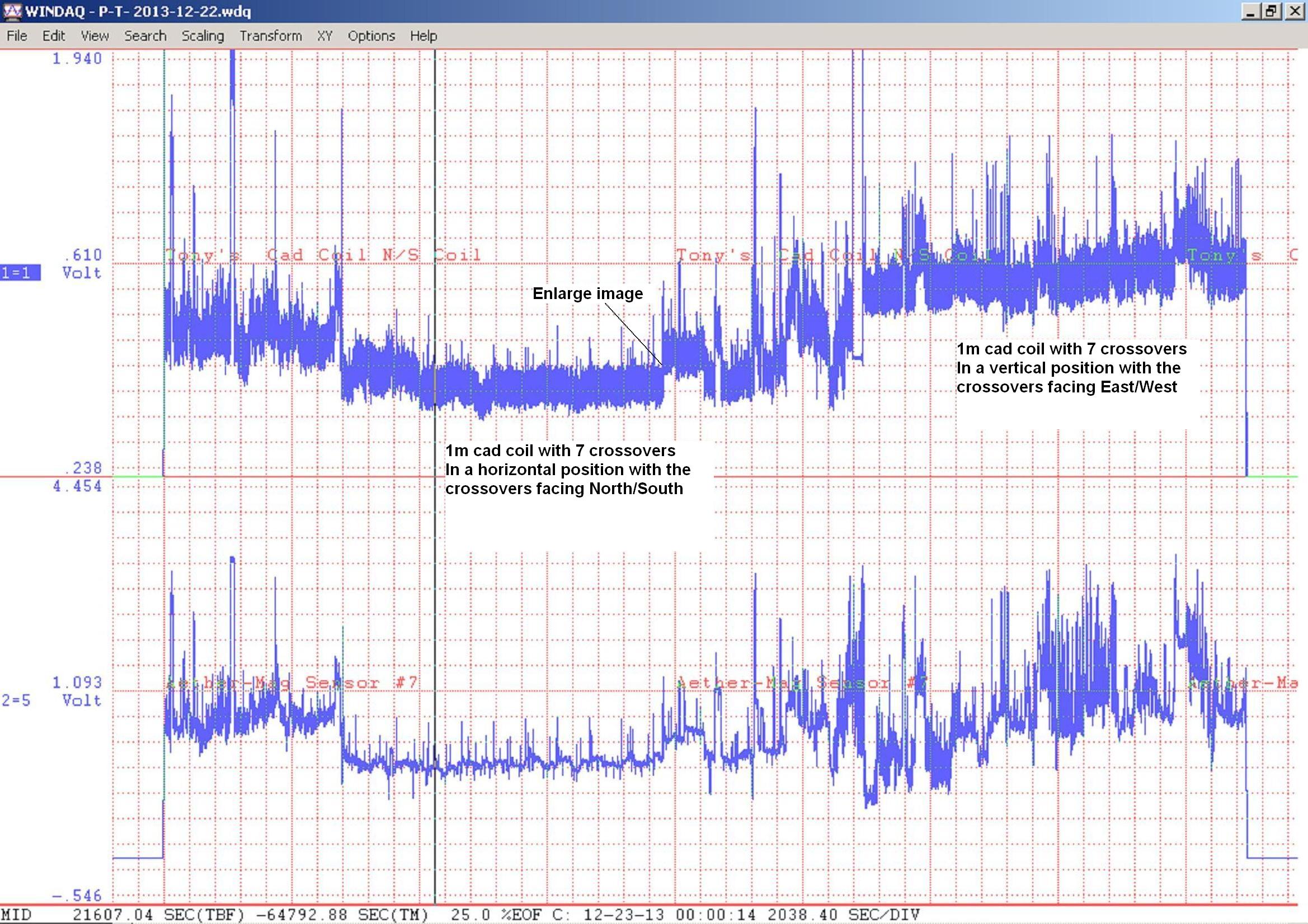
Sensors Tested – Unshielded Phone Wire Caduceus Coil (Sallur Coil) Caduceus coil on one channel and an Aether-Magnetic Sensor on the other channel. In all tests, the Caduceus Coil Cross Points were positioned facing North-South, as were the Aether-Magnetic transformer lamination edges. (The Aether-Magnetic transformer's flat sides, were positioned facing East-West.)
Circuit’s used – Caduceus Coil circuit and Aether-Magnetic sensor. Note this test setup uses a Dataq DI-148 Analog to Digital Converter and USB interface device. The software, is Windaq Chart Recorder, which is included with the Dataq device.
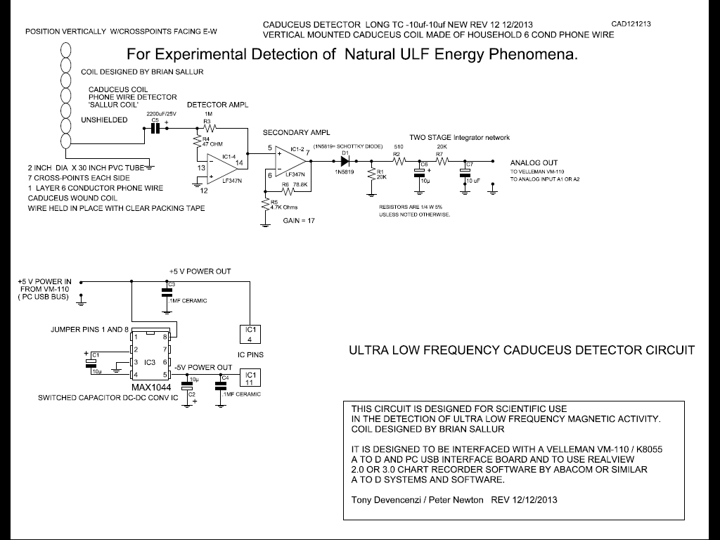
Caduceus Coil Circuit (Unshielded, Phone Wire, 6 Conductor, Vertical)
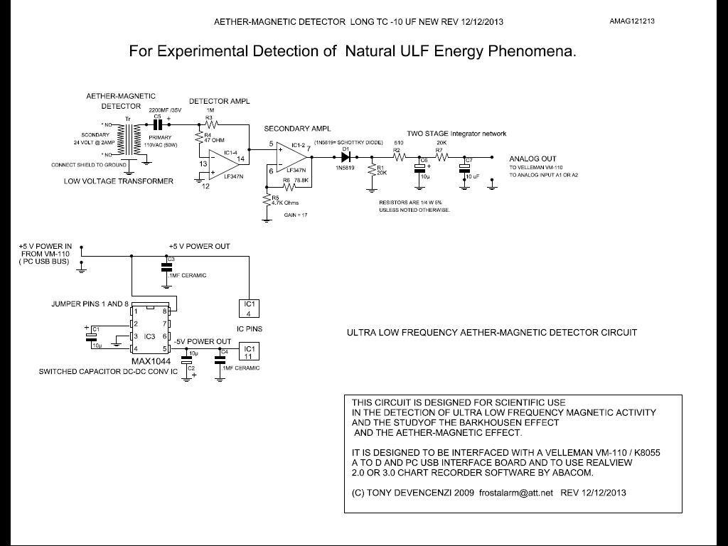
Aether-Magnetic Circuit \Circuits\amag121213.pdf
Duration of Test – 24 hours
Purpose of Test – To record activity detected by the caduceus coil and compare with Aether-Magnetic sensor.
Findings – Caduceus Coil tracks the Aether-Magnetic wave in general and with spike activity matches as well. Many of the individual spikes on the E-Field trace, matches Caduceus or Aether-Magnetic. It Does this with the Phone Wire Caduceus Coil either Vertical or Horizontal, but Vertical produces a higher output.
Result Images
Phone Wire Caduceus Coil 7 Cross Points (Sallur Coil) Photo

Caduceus Coil VS. Aether-Magnetic Sensor

Caduceus Coil VS. Aether-Magnetic Sensor Expanded Detail
.JPG)