Aether Theory and Observations
Involving Ultra Low Frequency Waves
Tony Devencenzi
frostalarm@att.net
Website Founded 2009-08-27
Last Revision 2024-06-30
2020 - 2024 Research
Page
1 of 24
Previous
Page
Next
Page
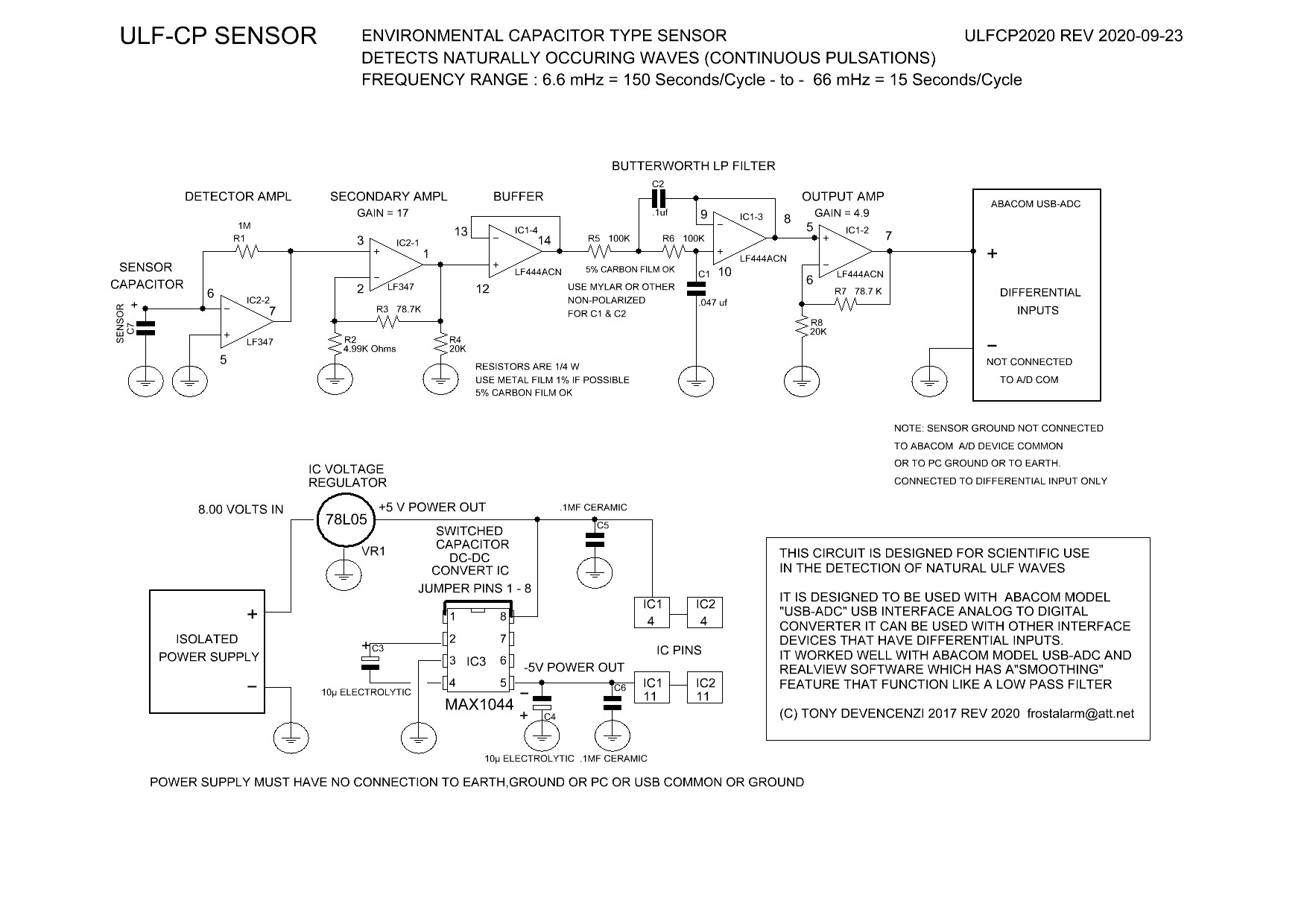
ULF-CP SENSOR
ULF Continuous Pulsation Sensor for Detection of Naturally Occurring Waves
What follows are the details, test results and construction information for a new type of sensor that detects naturally occurring continuous pulsation waves.
The purpose of this information is to provide a useful record of the development of this sensor and to aid anyone who wants to build
this device, as a tool to be used in studies of natural electrical phenomena.
I want to thank God for the gift of these discoveries and for His continually helping me, all of these years, or this research would not have been possible.
The sensor described here, uses a capacitor as the sensing element and detects naturally occurring continuous pulsations in the frequency range of 1 cycle every few minutes
to 1 cycle every few seconds. Most of the waves detected are in the range of: 1 cycle per 2 Minutes = 0.0083 Hz. (8.3 mHz) to 1 cycle per 15 Seconds = 0.066 Hz. (66 mHz).
The waves detected by my sensor are continuous pulsations that are naturally produced. They are present during the daylight hours as well as nighttime. The waves detected
with this sensor show a change of frequency at various times during the day and to a lesser extent, amplitude as well. Periods around or just after dawn and sunset, also have a
notable effect on wave shape and distortions of waves are seen, indicating that likely, the changing ion activity due to day / night transitions has a significant effect.
I believe the waves are naturally produced due to their changing frequency at different times of day and the distortions in symmetry that appear to be natural rather than
anything produced by man made sources.
This is a return to the waves that I first detected with my earliest sensor in 2009. That was before moving to long time constant averaging type sensors that were more
designed to record trends and peaks in activity rather than individual waves. The ULF-CP sensor is my latest development.
It is designed to monitor ULF waves in real-time and has a cleaner output than my earlier sensor, largely due to the use of true
differential operation and a higher resolution analog to digital converter.
A Note on Theorized Origin of the Waves:
NASA, NOAA and other research organizations around the world, routinely detect bands of ULF continuous pulsation
waves with satellite sensors and ground based equipment, that they call PC waves. These waves are thought to originate by influences of solar activity
such as solar flares, coronal mass ejections and more commonly, solar storms. These solar activities are believed to cause corresponding activity in the
Earths Magnetosphere which in turn stimulates the injection of ionized particles in the Ionosphere. This is thought to produce the continuous pulsation
waves by a complicated "hydrodynamic" process that I confess I dont really understand. This process must involve the circumference of the Earth, the speed of light
and other factors in wave propagation. I cannot prove the origins of the waves that these organizations detect and will not dispute their theories.
The IAGA ULF Range Designations:
In 1963 the International Association of Geomagnetism and Aeronomy (IAGA) introduced a classification scheme
I do not know if the waves detected by my sensors, are the same as those being detected by other organizations but, I believe they likely are, so I
will use their "PC" frequency range designations for uniformity.
Name: Period (sec): Frequency (mHz):
Continuous Pulsations
Pc1: 0.2-5 Seconds: 200 - 5000 mHz
Pc2: 5-10 Seconds: 100 - 200 mHz
Pc3 : 10-45 Seconds: 22.2 - 100 mHz
Pc4: 45-150 Seconds: 6.7 - 22.2 mHz
Pc5: 150-600 Seconds: 1.7 - 6.7 mHz
Irregular Pulsations
Pi1: 1-40 Seconds: 25 - 1000 mHz
Pi2: 40-150 Seconds: 6.7 - 25 mHz
Other CP Sensor Variations:
A few years ago, Peter and I tested two other variations of the sensor for ULF continuous pulsation waves.
Both of these sensors tracked the ULF continuous pulsation waves in real time. Each of these sensors had its drawbacks:
The Electric / Electrometer type picked up the ULF waves that are impressed upon the natural electric / electrostatic environment.
It used a very high impedance detection circuit with a Butterworth filter stage to remove higher frequency noise.
It would also pick up other electrostatic activity, such as walking across a carpet or air moving through an enclosed area
and would cause large spikes on the recording and contaminate the recorded graph of continuous pulsation waves.
The Magnetic CP type sensor picked up the ULF waves impressed upon the electromagnetic environment.
It used a magnetic induction coil circuit in Barkhausen mode with a Butterworth filter stage to remove higher frequency noise.
It would also pick up electromagnetic activity from appliances such as motors and fans in equipment,
which would contaminate the recorded graph of continuous pulsation waves.
The ULF-CP Capacitor type sensor is less susceptible to electrostatic or electromagnetic interferance, so it was the first one that is presented here.
Amag-CP Magnetic Sensor Added 02/03/21. This improved sensor still has some, though now reduced, susceptibility to electromagnetic interference
but, I believe, in its present form, it can provide a useful comparison to the waves detected by the ULF-CP Capacitor type sensor. Please see details of this
sensor on pages 14 and 15 of this update.
Sallur Coil-CP Ionospheric Sensor Added 07/10/23. This is a sensor based on Brian Sallur's Phone-Wire Caduceus design and is
coupled with my ULF-CP Capacitor sensor amplifier electronics. Its purpose is detect, monitor and record, ionospheric magnetic continuous pulsation
activity. Please see the details of this sensor on pages 17 and 18 of this update.
ESV-CP Electrostatic Sensor Added 08/15/23. This improved electrostatic sensor is based on a circuit that extracts the ULF
Continuous Pulsation activity from the electrostatic environment. Please see the details of this sensor on pages 19 and 20 of this update.
Dual ULF Sensor System Added 09/30/23: This two channel system extracts the ULF Continuous Pulsation activity from the
electrostatic environment as well as the AC power grid. Please see the details of this new sensor on pages 21 through 24 of this update.
Back To the ULF-CP Capacitor type Sensor and Research
.
ULF-CP Sensor basic circuit description: A capacitor is used as the detecting element. When exposed to ultra-low frequency waves, the capacitor frees electrons and generates
a tiny voltage that corresponds to the waves being detected. This signal of only a few micro-volts is fed to a very high gain amplifier, the output of which is in turn fed to a second
(non-inverting) amplifier stage. This amplified output is then sent to a Butterworth Low-Pass filter circuit that removes most of the higher frequency noise. Finally there is one last
(Non-Inverting) amplifier stage. The output is then fed to an analog to digital converter unit that has a USB interface, to connect to the USB port of a personal computer. The PC
runs a software program that displays and records the waves graphically as a chart recorder and saves the recording to a file.
Proving that the waves are not being produced by the sensor itself as self-oscillations: When multiple sensors are constructed and each fed to a separate differential input
channel of the USB-ADC Analog to Digital converter, the waves track each other in real time. This is still true even if widely different microfarad values of sensing capacitors
are used in each sensor. When separate sensors, again, even with widely different values of sensing capacitor used on each sensor, are connected to different
USB-ADC units and each USB-ADC unit is in turn connected to a separate personal computer, each running its own instance of RealView, the waves on
each monitor still track in real time.
As described above, this sensor uses a Butterworth Low Pass filter stage, to remove most of the higher frequency noise in order to reveal the ULF wave. The two capacitors
C1 and C2, in this stage, were chosen after much experimentation, to be the best for extracting the ULF continuous pulsation waves. In experiments, smaller values of
capacitors were tried as well as larger. With much larger values, the wave amplitude is reduced, however the frequency and wave shapes are not affected. With smaller values,
amplitude is greatly increased, as well as detected noise but again, the frequency and wave shapes were not affected. This is proof that the detected waves are not simply
the result of a tuned low-pass filter shaping noise into a waveform.
What makes this sensor different from the ones we have made in the past such as the Aether-Magnetic sensor, E-Field sensor and earlier Capacitor sensors?
(1) Earlier sensors were single-ended devices which had their power supply Negative terminals tied to power supply earth / ground, personal computer earth / ground etc,
They, could tap into and use the 5 Volt line on the personal computer's USB bus for power, or could be powered by a ground referenced external power supply if desired.
The new ULF-CP Sensor requires a power supply that is completely Floating, whose negative (as well as positive) terminal has no connection to earth / ground or personal
computer ground.
The ULF-CP Sensor has a built in 78L05 5 Volt IC Regulator and is powered by a well regulated, Isolated, bench type power supply. I am presently using a GW Instek model
GPD-3303S Programmable lab bench type power supply, to power this sensor. I have it set for 8.000 Volts power to the input of the 78L05 5 Volt regulator. Almost any good
stable, well regulated, adjustable, bench type power supply should work ok too, as long as its outputs are isolated from earth / ground. The current drawn by the ULF-CP Sensor
is only around 21 mA. Using a precision regulated power supply, to in turn power the 78L05 voltage regulator, is probably over-kill. I just want to make sure that
the power to the sensor is very stable and any possible influence of power fluctuations on the recorded waves can be completely eliminated.
A 9 Volt battery feeding the 78L05 regulator would probably work ok, as long as you replace it when the battery voltage drops below 7.5 Volts.
In the case of setups using more than one sensor (such as comparing the output of different capacitors simultaneously while recording on multiple channels),
each sensor must have its own separate isolated power source (isolated power supply channel or separate battery) , otherwise the sensors outputs will interfere with each
other and produce distortion due to cross talk. For example, the GW Instek GPD-3303S mentioned above has more than one channel of power out and each channel
is electrically isolated from the others.
Another power option for multiple channel setups, could be to use separate, electrically Isolated, DC to DC converters to power each channel, with a common power supply input.
The DC to DC converters' outputs must be electrically isolated from the input power source and must have a stable low noise output.
(2) Earlier sensor designs, mainly used the Velleman VM-110 Analog to Digital Converter / USB interface board. This is a single ended device that can't accept differential signals.
This new ULF-CP Sensor uses true differential operation and requires an Analog to Digital converter that can handle differential inputs. For this sensor, the Abacom
model called USB-ADC Analog to Digital Converter / USB Interface is being used. This device has the ability to accommodate up to 4 differential channels and
works with Abacom's RealView chart recorder software. Abacom's RealView as well as their USB-ADC interface device are available
on their website: https://www.electronic-software-shop.com/index.php
(3) Most earlier sensor designs, used a Long-Time-Constant averaging circuit to record the voltage changes over several hours. This new sensor uses a
Butterworth Low-Pass filter circuit to remove higher frequency noise and bring out the ULF wave. This sensor is designed to display and record the waveforms
in realtime rather than use the long term averaging method like in our Aether-Magnetic, E-Field and (earlier) Capacitor sensors.
Please note: The author and aetherwavetheory.com are not affiliated with Abacom,
Velleman, Instek or any other electronic parts, software suppliers or test equipment manufacturers and do not receive any compensation from them.
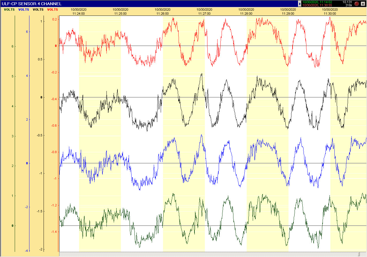
Click here for a clearer ( PDF ) of diagram
Example of a RealView four channel (differential) recording setup. This is the same setup that was used
in the four channel comparison test recordings of capacitor groups on the following pages,
Sample rate was set to 100mS and each channel's trace "Smoothing" setting was set to "Medium".
The four capacitors that were tested in this example were: Red = FT-3 Teflon .1 uF / 600 V, Black = FT-3 Teflon .22 uF / 600 V,
Blue = MPG-P Polystyrene 2 uF / 250 V, Green = MPGO Polystyrene 8 uF / 160 V. The area to the Left of the graph, shows the output voltages of each sensor.
Capacitor Tests:
An important part of the research on this sensor was to try to find the best electrical value, physical size, and dielectric type, for use as the sensor capacitor.
This was done not only to find the best capacitor but, also in hope of learning more about the nature of the waves being detected. To that end a number of different capacitors
were obtained and tested. A total of 99 capacitors were tested in this sensor. The results of those tests are summarized here.
A RealView recording sample for the most interesting capacitors in each group is provided along with a brief description of the test results, for each capacitor in that group,
sufficient for comparison. Also included are conclusions for each test group. Photos of all capacitors tested are included for your reference.
In the tests, note is made of Sensor Circuit Output Voltage. It should be noted here, that the actual wave voltage out of a capacitor would only be a few microvolts.
The Sensor Circuit Output Voltage is referring to the voltage out of the entire sensor circuit, after all stages of amplification, as measured by the USB-ADC analog to digital
converter. This figure is a good means of capacitor output amplitude comparison.
As you will see, many types and values of capacitors will work as sensors of these ULF continuous pulsation waves.
A number of types tested have working voltage ratings of from a few hundred to several thousand volts. These high
voltage rated values were chosen so they would have much larger physical size, for a given microfarad value, which
gives higher output. Larger physical size capacitors generally are higher output than physically smaller ones for a given capacitance value.
Obviously, the ability of a capacitor to work at high voltages is not relevant here, since the capacitor, working as a sensor, has only a very small voltage on it.
Most non-polarized capacitors exhibit a higher output voltage when their terminals are connected one way: one terminal to sensor input, one terminal connected
to the sensor floating ground, than the other way. For some capacitors the difference is small, for others the output with the higher output connection is quite large.
These differences have been recorded in the test data. Because a non-polarized capacitor doesnt have its terminals marked, The following convention was created:
With a capacitor (tubular, square or other shape) facing you so you can read its label, Terminal 1 is on
the LEFT and Terminal 2 is on the RIGHT. Note: For the Russian Teflon FT-2 and FT-3 series and the Russian Polycarbonate K77-1 series the label is printed sideways
on the tubular cylinders but, there is a capacitor symbol printed near one end. That end is considered Terminal 2 for our connections here. Why a non-polarized capacitor
should actually behave as polarized in this sensor application is not known but, it obviously has something to do with internal construction.
It was discovered that a metal cased capacitor with its case not connected to either terminal, detects the wave just as well, if not better than a non-metallic
cased capacitor however, if you connect a normally floating metallic case to either the sensor (floating) ground, or earth ground, that will usually stop the capacitor from
detecting the wave.
The exception of this is for polarized electrolytic and larger Tantalum capacitors which have their metal cases normally connected to their Negative terminal.
An additional exception is some non-polarized capacitors that are made so that they have their metal cases connected to one terminal. These seem to work
fine with their case connected to the sensor circuits floating ground.
The physical positioning of a sensor capacitor also appears to influence its sensitivity. With tubular types, tests were performed with the capacitor ends pointing
East and West. For square type packages, the capacitor was positioned with its terminals pointing East and West, unless otherwise described in the test data.
Each capacitor used in the sensor tests, was first tested on an Instek model LCR-821 High Precision LCR Meter.
The test frequency was set to 1000 Hz. This test was to determine that the capacitor was functional, within rated tolerance and to find its dissipation factor.
Please note: In the tests that were performed to acquire the data listed for each capacitor, only a two channel setup was used, with only the Standard Capacitor on Channel 1
and one Capacitor under test on Channel 2, at a given time. The four channel comparison sample tests were made at a later time, so the exact voltages may not match the ones
made earlier, due to time of day or the amplitude of the waves present at any particular time. The output differences in wave quality or amplitude can still be clearly seen.
Please see the newly discovered exceptions, in the summary on each page and the final summary on page 11.
New Discoveries and Updates:
New Discoveries October 15, 2021: As described on Project Summary Page 11 and Construction Notes Page 12.
It was discovered that the workbench I used (steel covered with Formica) affected the output signal amplitude of the sensor capacitors, considerably.
This discovery is important to take into consideration when evaluating the test results presented here.
This also presents an opportunity for future research into the behavior and origin of the detected waves.
New Discovery December 31, 2021: The natural ULF Continuous Pulsation waves can propagate via power transmission lines and are induced into the insulated
steel desk top, which are then detected by the capacitor sensors. Please read Page 11 Project Summary for details.
New Discovery January 15, 2022: ULF-CP Antenna-Box-Capacitor Sensor - Improved Detection Scheme.
After the discovery that my Formica covered steel work bench actually functions as a part of the sensor capacitor's detection
apparatus, I needed too eliminate the need for the steel work bench, to make the sensor more portable and useable for those
who do not have a steel work bench. Please see the ULF-CP Antenna-Box-Capacitor Sensor on Project Summary Page 11
and Construction Notes Page 12. This new sensor variation solves this problem and reveals new information and questions about ULF wave transmission.
New Page added June 10, 2022: Antenna-Box-Capacitor Sensor Construction Notes Page 12A
Addendum to Project Summary Page 11 added June 10, 2022: 'The HAARP Question'
Addendum to Project Summary Page 11 added November 20, 2022: 'Observations and Conclusions' Analysis of main sensor types function and usefulness.
Propagation of CP waves via power grid, power company distribution and utility power mains and building power mains wiring.
New Sensor Added July 10, 2023: Introducing the Sallur Coil-CP Sensor. This is a sensor based on Brian Sallur's Phone-Wire Caduceus design and is coupled
with my ULF-CP Capacitor sensor amplifier electronics. Its purpose is detect, monitor and record, ionospheric magnetic continuous pulsation activity.
Please see the details of this new sensor on pages 17 and 18 of this update.
New Sensor Added August 15, 2023: Introducing the ESV-CP Sensor. Improved electrostatic sensor based on a circuit that extracts the ULF
Continuous Pulsation activity from the electrostatic environment. Please see the details of this new sensor on pages 19 and 20 of this update.
New Sensor Added September 30, 2023: Introducing the Dual ULF Sensor System. This system extracts the ULF Continuous Pulsation activity from the
electrostatic environment as well as the AC power grid. Please see the details of this new sensor on pages 21 through 24 of this update..
New Page Added May 1st, 2024: Shows Dual Sensor System reacts to Earthquake and Eclipse. Please see page 24A of this update for details.
New Page Added June 30, 2024: Shows Dual Sensor System recording May 2024 Geomagnetic Storm. Please see page 24B of this update for details.
Sensor Tests. This data was recorded for each capacitor:
- Model number:
- Make or country of manufacture / Date of manufacture:
- Dielectric type:
- Casing material (M=Metallic / NM=Non-Metallic):
- Shape and Physical size:
- Capacitance value:
- Rated Tolerance:
- Working Voltage rating:
- Dissipation Factor:
- Sensor Circuit Output Voltage in each of two connection configurations:
Terminal 1=Input / Terminal 2= Floating Ground: Pk-Pk
Terminal 2=Input / Terminal 1= Floating Ground: Pk-Pk
- Comments on observed waveform quality or other notable behavior:
_______________________________________________________
A note about Sensor Output Voltage: Because the output changes somewhat throughout the day, this measurement is not a precise one but, should be good for comparison.
For the Sensor Capacitor Four Channel test series, a sensor circuit with a Standard capacitor was recorded on channel One
of the USB-ADC (Red Trace), while the remaining channels recorded the other sensor circuits with capacitors under test as for comparison.
The Standard capacitor used in these tests was:
- Model number: FT-3
- Make or country of manufacture / Date of manufacture: Russia / 9112
- Dielectric type: Teflon Film
- Casing material (M=Metallic / NM=Non-Metallic): M
- Shape and Physical size: Tubular, Axial / 26 mm Dia X 32 mm Length
- Capacitance value: 0.1 uF (100 nF)
- Rated Tolerance: 5%
- Working Voltage rating 600V
- Dissipation Factor 90 PPM
- Sensor Circuit Output Voltage in each of two connection configurations:
Terminal 1=Input / Terminal 2= Floating Ground 350 mV Pk-Pk
Terminal 2=Input / Terminal 1= Floating Ground 750 mV Pk-Pk
- Comments on observed waveform quality or other notable behavior:
Very good clean waveform.
_______________________________________________________
Capacitors tested are listed mainly by dielectric type group.
When examining the various four channel recordings, please remember that the recordings were made
at different times of the day, when the detected waveforms may have been more or less symmetrical
and may have had more or less spikes and noise, as well as different pulse widths. Always use the Standard
FT-3 Teflon Film capacitor (Red Trace), as a comparison control when judging the performance of a capacitor under test.
2020 Through 2023 Update Pages:
Page 1 - Introduction to the ULF-CP sensor
Page 2 - Group 1, Polystyrene Film Capacitor Tests
Page 3 - Group 2, Teflon Film and Group 3 Silver-Mica Capacitor Tests
Page 4 - Group 4, Special and Unusual Types Capacitor Tests
Page 5 - Group 5, PIO (Paper in Oil) Capacitor Tests
Page 6 - Group 6, Hybrid (Paper, Oil, Combined with Plastic Film) Capacitor Tests
Page 7 - Group 7, Tantalum Capacitor Tests
Page 8 - Group 8, Electrolytic Capacitor Tests
Page 9 - Group 9, Polycarbonate Capacitor Tests
Page 10 - Group 10, AVX / TCP Medium and High Power Polypropylene Film Capacitor Tests
Page 11 - Project Summary - (Added 2021-10-15, 2021-12-31, 2022-01-15, 2022-06-10, 2022-11-20, 2023-08-15, 2023-09-30)
Page 12 - Construction Notes - (Added 2021-10-15, 2021-12-31, 2022-01-15, 2022-11-20, New AC Probe Variation 2023-09-30)
Page 12A - Antenna -Box -Capacitor Sensor ABC Construction Notes - ( Added 2022-06-10, New AC Probe Variation 2023-09-30)
Page 13 - ULF Wave Scope 2020 Program (New 2021-01-09)
Page 14 - AMAG-CP Sensor Aether-Magnetic Variation (New Variation 2021-02-04)
Page 15 - AMAG-CP Sensor Construction Information (New Variation 2021-02-04)
Page 16 - ULF Wave Scope 2021 Program (New Variation 2021-02-04)
Page 17 - Sallur Coil-CP Sensor Introduction (Page Added 2023-07-10)
Page 18 - Sallur Coil-CP Sensor Construction Details (Page Added 2023-07-10)
Page 19 - ESV-CP Electrostatic Sensor Introduction (Page Added 2023-08-15)
Page 20 - ESV-CP Electrostatic Sensor Construction Details (Page Added 2023-08-15)
Page 21 - Dual ULF Sensor System Introduction (Page Added 2023-09-30)
Page 22 - Dual ULF Sensor System: Electrostatic Sensor and Main Unit Construction (Page Added 2023-09-30)
Page 23 - Dual ULF Sensor System: Power Grid ULF Sensor Construction (Page Added 2023-09-30)
Page 24 - Dual ULF Sensor System: RealView Software Notes (Page Added 2023-09-30)
Page 24A - Dual ULF Sensor System: Reacts to Earthquake and Eclipse (Page Added 2024-05-01)
Page 24B - Dual ULF Sensor System: Geomagnetic Storm Recording and Unexplained Phenomena (Page Added 2024-06-30)
Page
1 of 24
Previous
Page
Next
Page
www.aetherwavetheory.com